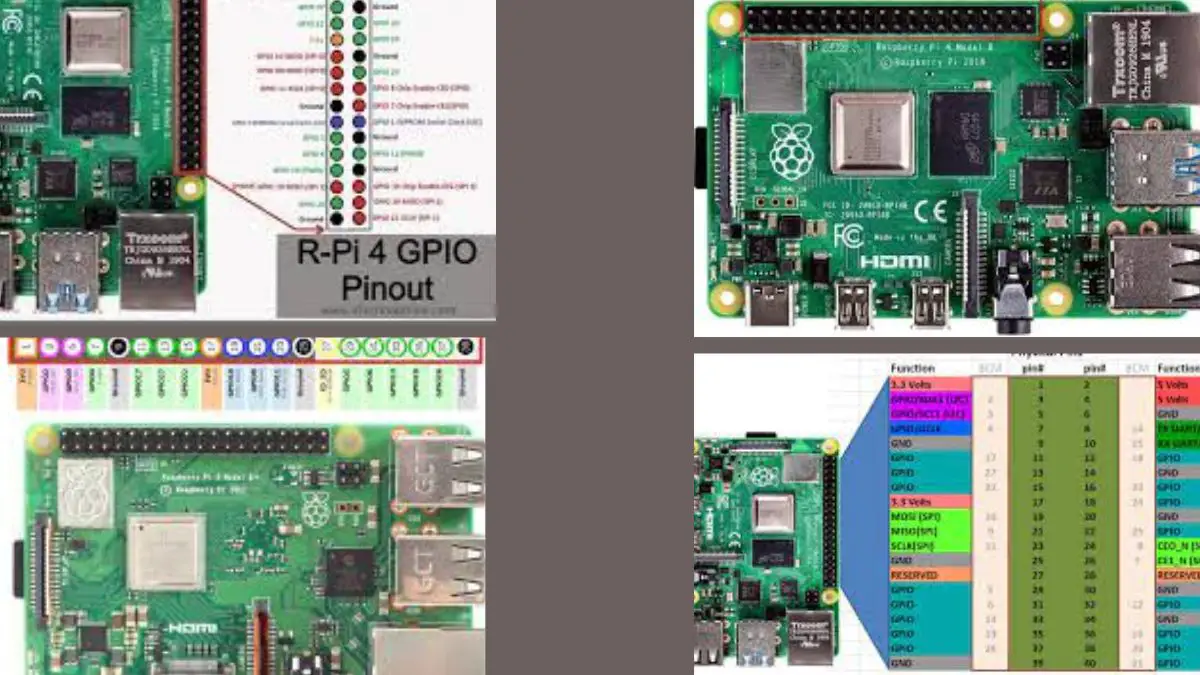
Raspberry Pi 4 came out in 2019 and offered the world a mini-masterpiece in the tech world.
Better than ever before, Raspberry Pi 4 enjoyed an upgrade in almost every aspect, from the processing speed to more memory, and of course, the 40 pins that Raspberry Pi has been offering since their B+ model.
In this guide, we will break down Raspberry Pi 4, each and every pin of the model, so that you can make the best use of it to create awesome robots and smart appliances.
Let’s start with the 40 GPIO pinout structure of Raspberry Pi 4.
Table of Contents
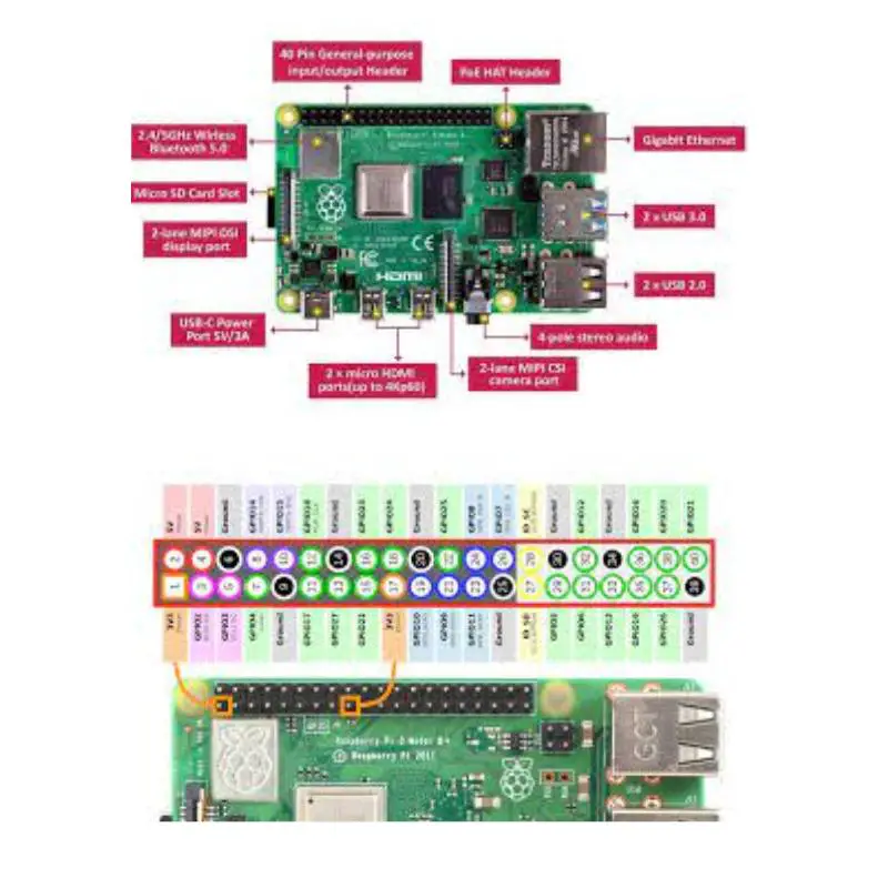
The 40 Pins On Raspberry Pi 4 Explained
Here are all the pins that you will find on Raspberry Pi 4.


- GPIO (General Purpose Input)
- SPI (Serial Peripheral Interface)
- I²C (Inter-integrated Circuit)
- UART (Universal Asynchronous Receiver/Transmitter)
- Pulse Width Modulation
- Ground
- 5v (Power)
- 3v (Power)
Here is how they’re all laid out on the Raspberry Pi 4.
| 3v Power | 5v Power |
| GPIO I²C | 5v Power |
| GPIO I²C | Ground |
| GPIO | GPIO UART |
| Ground | GPIO UART |
| GPIO | GPIO PWM |
| GPIO | Ground |
| GPIO | GPIO |
| 3v Power | GPIO |
| GPIO SPI | Ground |
| GPIO SPI | GPIO |
| GPIO SPI | GPIO SPI |
| Ground | GPIO |
| GPIO I²C | GPIO I²C |
| GPIO | Ground |
| GPIO | GPIO PWM |
| GPIO PWM | Ground |
| GPIO PWM | GPIO |
| GPIO | GPIO |
| Ground | GPIO |
GPIO Pins
Out of 40 pins that the Raspberry Pi 4 has, 26 of them are GPIO.
If you’re already a Raspberry Pi fan, it’s very unlikely that you haven’t come across GPIO pins, but for the sake of our guide, let’s start with GPIO.
GPIO (General Purpose Input/Output) pins help you accept and send information in and out of the device by acting as inputs and outputs as well.
Some pins serve the purpose of acting as inputs, affording voltages at different capacities, while the other ones have the sole purpose of outputs.
SPI Pins
SPI (Serial Peripheral Interface) Pins are used to communicate between sensory devices.
The Raspberry Pi 4 sends and accepts the data from the same pins, acting as the MOSI and MISO.
The SPI is actually similar to the I2C pins, however, SPI is used more for short-distance purposes. Examples are an SD card or a microcontroller.
I²C Pins
The I²C (Inter-integrated circuit) pins help the device control other peripheral devices that are attached to Raspberry.
The handshake between the two devices works through the technologies of SDA (Serial Data) and SCL (Serial Clock).
SDA forwards the data to the other device while the SCL controls the processing speed of the data.
Examples of connections to the I²C pins are LCD screens or temperature sensors.
UART Pins
UART )Universal Asynchronous Receiver/Transmitter) pins transfer data sequentially i.e. bit by bit.
Except for the 2 UART pins at positions 8 and 10, there are 4 more pins that you can use for UART communication.
However, this will require you to enable them by launching the boot configuration file.
Ground
The ground is where you measure all voltages. It also serves as the completion of electrical circuits.
Remember to make connections with the Ground before connecting it to the power to avoid accidents.
PWM Pins
PWM (Pulse Width Modulation) pins serve the purpose of converting digital signals into analogue signals.
All the pins can help with software PWM, but only pins number 12, 13, 18, and 19 can help with hardware PWM.
Conclusion
I have now explained the purpose each of the pins on the Raspberry Pi 4 pinout serves.
You should now have the knowledge to play around and create exciting new projects with the device.
Be sure to be careful, and good luck!

